Visualizing 3D Matrix Rotations
The introduction to the second chapter of The Art of Electronics bemoans the traditional treatment of transistor models where “circuit behavior tends to be revealed to you as something that drops out of elaborate equations, rather than deriving from a clear understanding in your own mind as to how the circuit functions…” The chapter goes on to build both a mental model (“transistor man”) and a set of equations (Ebers-Moll) in parallel.
I like this philosophy: knowing how to compute something is not the same as understanding how it works. Nor is a mental model useful without the math to apply it. The two are necessary complements.
Richard Feynman talks about a similar idea in this lecture, pointing out that most physicists keep many different models of the same concept in their head–even though the results are mathematically equivalent–because the models give different intuitions.
With that in mind, behold:
This is a 3D rotation matrix (3D graphics often use 4x4 matrices, which include translation and perspective information, but I’ve omitted that here for simplicity. These ideas can be extended to a 4x4 matrix).
For a long time this was black magic for me. Though I used it, I didn’t really understand it. Most of the books I read on 3D graphics treated it opaquely. I tried to work through it by expanding it into algebraic equations, but those were even more inscrutable.
The problem was that I was treating the matrix as nothing more than a more compact way to represent a bunch of equations. But the matrix form can be an intuitive model for visualizing operations. One way of thinking about a matrix is to treat each column as a vector:
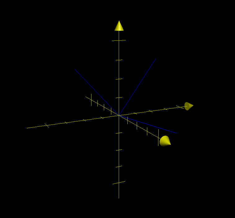
Plotting these three vectors reveals something interesting:

To wit:
- Each of these vectors is the same length (they are length 1 in this case because the matrix is not scaled)
- All the vectors are at right angles to each other.
These properties are true for any rotation matrix. The graph looks almost like… a coordinate system. In fact, it is a rotated coordinate system. Each vector represents an axis: x, y, and z.
We usually multiply a rotation matrix by a vector which contains the coordinates of the point we want to translate. It is written like this:
One way of thinking about matrix/vector multiplication is that we are taking each column of the matrix and multiplying it by the corresponding row of the vector, then adding the resulting vectors together. This is referred to as a linear combination of the columns, and is a fundamental idea in Linear Algebra. We can rearrange it like this:
This is equivalent to other descriptions of how to multiply matrices and vectors, it just gives us another way of thinking about the operation.
A few other properties of vectors are useful to understand:
- When we multiply a scalar (non-vector) times a vector, we get a new vector that is the same direction, but whose length is multiplied by the scalar (Each of these vectors in this example has a length of one, so the length of the new vector values will be the scalar coordinate).
- We can visualize addition of two vectors by attaching the tail of one vector to the head of the other.
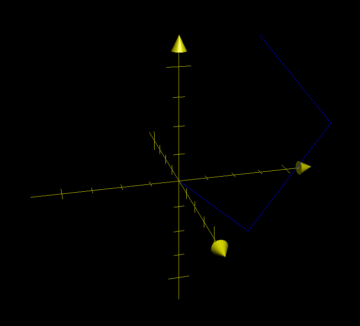
Putting these ideas together, this product moves x units along the x axis, y units along the y axis, and z units along the z axis. It looks like this:

Although it may be hard to see on this plot, the three vectors are still at right angles to each other.
A 3D rotation matrix transforms a point from one coordinate system to another. The matrix takes a coordinate in the inner coordinate system described by the 3 vectors and and finds its location in the outer coordinate system.
We can extend this model to think about concatenating rotation matrices. When we multiply two rotation matrices, the result is a new matrix that is equivalent to performing the two rotations sequentially.
There’s an example in my Quake level viewer:
1
2
3
4
    if (gKeyPressed[kRightArrow])
        gCameraOrientationMatrix *= kRotateRight;
    else if (gKeyPressed[kLeftArrow])
        gCameraOrientationMatrix *= kRotateLeft;
gCameraOrientationMatrix indicates which direction the camera is pointing in the scene. When the user presses the right key, I multiply the current orientation by kRotateRight, which is a constant matrix that is rotated slightly right. The result is that each update rotates the gCameraOrientationMatrix a little more.
Another way of expressing matrix multiplication is to multiply each of the column vectors of the second matrix by the first matrix, then stick all the resulting vectors back together. So if we have two matrices:
The product AB is:
This takes each of the axes of the second coordinate system (B) and rotates them by the first coordinate system (A), putting them inside it.