Life of a Triangle
A few years ago, Broadcom released full specifications for their VideoCore IV GPU, which is in the system-on-chip on the popular Raspberry Pi dev board. Before this, most details of commercial GPUs were secret. Although GPU manufacturers released white papers and some academic publications, they were often greatly simplified and lacked important details.
https://www.broadcom.com/docs/support/videocore/VideoCoreIV-AG100-R.pdf
The documentation is detailed, but is organized by functional block, which makes it hard to see how everything fits together. To understand it better, I traced the path of drawing commands all the way through the pipeline. I’ve attached my notes here. I’ve based this on my reading of the documentation, but haven’t verified it by running on hardware, so there are probably inaccuracies. If anyone knows better, please feel free to post corrections in the comments. I’ve also omitted some details to keep the big picture clear, but I’ve annotated this with references to the documentation to make it easy to flip back and forth.
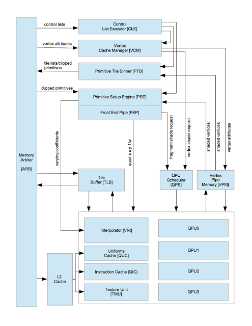
Below, I’ve recreated the overall block diagram from the VideoCore documentation (figure 1, p. 13). I’ve simplified it a bit and removed components that aren’t used for 3D rendering, i.e. general purpose computation and OpenVG.

Background
The memory arbiter on the left side of the diagram routes reads to and writes from system memory (SDRAM). Like most mobile GPUs, VideoCore uses a unified memory architecture–the CPU and GPU share the same memory.
VideoCore uses a tile based rendering architecture. It divides the screen into squares and renders them one at a time. The GPU stores the tile it is currently rendering in on-chip memory and copies it to external memory once it has completely rendered it. This differs from an “immediate mode” renderer, which writes pixels to external memory as it computes them and writes the same destination location multiple times if there are overlapping triangles. The advantage of a tile based architecture is that it reduces GPU memory bandwidth, which is important because the GPU shares memory with the CPU.
Rendering occurs in two passes. The first (binning) creates a list for each tile of the polygons that overlap it. The second (rendering) then fills in the pixel data for them.
CPU Scene Setup
The CPU controls the GPU using control registers that are memory mapped into the CPU address space (Section 10) and shared memory control lists. Each control list is is a contiguous array of control records (Section 9).
Actually, there is another processor inside the VideoCore that acts as a proxy between the CPU and GPU. This is not covered in the linked documentation. I’ll use the term “CPU” to refer to the combination of the host processor and this proxy.
There are two types of rendering calls:
- State Updates: OpenGL Calls like glBindBuffer and glUseProgram do not draw anything to the screen, but control rendering of subsequent primitives.
- Draw Calls: glDrawElements and glDrawArrays draw polygons.
When the state changes, the CPU enqueues a GL Shader State control record (p. 69) in the control list. The driver combines multiple state changes into a single control record where possible. This control record contains a pointer to the Shader State Record (Table 45, p. 78), which other control GL Shader State records may also reference (this indirection avoids extra copies when draw calls span multiple tiles). The Shader State Record contains pointers to vertex attribute arrays, shader code, and uniforms.
Draw calls enqueue an Indexed Primitive List record (p. 68) in the control list, which contains the vertex indices that were passed into the glDrawElements call.
When the CPU has submitted all commands for the frame, it writes the V3D_CT0CA register (p. 82), which points to the system memory address of the control list it just created. It then writes the control list executor control register (V3D_CT0CS, p. 85), setting the CTRUN bit to 1. This causes the Control List Executor (p. 62) to begin fetching the control records the CPU just wrote.
Binning Pass
This pass creates a new control lists for each tile that contain the polygons overlap it. The next pass will uses these control lists to render the tiles.
The Command List Executor starts by walking through all commands in the command list that were submitted by the CPU. When it executes the GL Shader State command, it reads the Shader State Record that it points to and programs the Vertex Cache Manager with the address, format, and stride of the current vertex buffer objects. When it reads a Indexed Primitive List command, it streams the indices to the Vertex Cache Manager, which fetches them from system memory and writes them into Vertex Pipe Memory (VPM). Vertex Pipe Memory is a chunk of on-board SRAM that is used to store both the inputs and outputs from vertex shaders. The Vertex Cache Manager caches vertices that are referenced multiple times and avoids re-computing them. The Quad Processor Unit (QPU) executes 16 shader instances at a time, so when the Vertex Cache Manager has accumulated all the attributes for 16 vertices, it sends request to the QPU scheduler to run the coordinate shader on them.
The coordinate shader (p. 14) is a stripped down version of the vertex shader, created by the shader compiler, that only computes the positions of the vertices. At this stage, we don’t need other attributes like normals.
Section 3 describes the QPU (Quad processor), which executes the shader programs. It is 16-way SIMD. The QPU scheduler starts a shader program when an external unit requests it. When the program completes, it terminates with an instruction that has its signaling field to 3 - Program End (p. 29). This halts the QPU until the QPU Scheduler starts another program on it.
The QPU reads and writes vertex attributes/parameters in Vertex Pipe Memory using special purpose registers 48-50 (VPM_READ, VPMVCD_RD_SETUP, VPMVCD_WRITE, VPMVCD_WR_SETUP), as described on Page 57. The coordinate shader reads the vertex attributes from vertex pipe memory, translates them, and stores the computed vertex position back to a different location in Vertex Pipe Memory.
Given a simple vertex shader in GLSL:
uniform mat4 mvp;
attribute vec4 position;

void main()
{
    gl_Position = mvp * position;
}
I’m assuming the 4x4 matrix is stored as an contiguous array of floating point uniform values. The Shader State Record (bytes 20-23) stores the base address of the current set of uniforms and there is a small hardware cache for them. The shader reads these from register 32-A (UNIFORM_READ, p. 37). Each read to this register pulls the next uniform out in order. For a vertex shader, the shader is set up to automatically fetch the vertex attributes in the proper format via the VPM_READ register. Given this, the vertex shader would presumably look something like this (The documentation does not specify an assembly format, but I use the syntax similar to this sample code):
    .set VPM_READ, ra48
    .set VPM_WRITE, ra48
    .set UNIFORM_READ, ra32

    mov ra5, VPM_READ          # read position[0] into temp reg
    mov ra6, VPM_READ          # read position[1]
    mov ra7, VPM_READ          # read position[2]
    mov ra8, VPM_READ          # read position[3]

    mov r2, 4                  # Loop count
row_loop:
    fmul r0, UNIFORM_READ, ra5 # mvp[n][0] * position[0]
    fmul r1, UNIFORM_READ, ra6 # mvp[n][1] * position[1]
    fadd r0, r0, r1
    fmul r1, UNIFORM_READ, ra7 # mvp[n][2] * position[2]
    fadd r0, r0, r1
    fmul r1, UNIFORM_READ, ra8 # mvp[n][3] * position[3]
    mov VPM_WRITE, r1          # Store in gl_Position[n]
    sub r2, r2, 1              # Decrement row count
    brr.allnz row_loop         # If not zero, loop for next row

    exit                       # End program. sig bits = 3 (p. 29)
The Primitive Tile Binner reads these values for each primitive from Vertex Pipe Memory. It determines which tiles the primitive overlaps and appends it to the control list for each one. It writes these control records out to system memory. A single draw call may contain many primitives, only some of which may overlap the tile. The PTB writes a Compressed Primitive List command into the new command stream that contains indices of the primitive that overlap (p. 72). It may also clip them and write new vertex coordinates (Clipped Primitive, p. 78). The driver on the CPU side allocates a chunk of memory for the Primitive Tile Binner to store the new commands into and passes it to hardware through the V3D_BPCA register (p. 82).
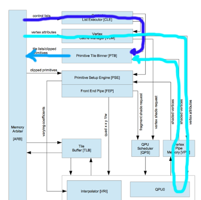
Here is the architecture diagram annotated with the flow of data during the binning pass. The blue arrow represents the path of the vertex indices and the cyan the path of the vertex positions. The Primitive Tile Binner takes these two and writes a new control list back to memory via the light blue arrow.

At the end of the control list is a Halt command record (p. 66). When the Command List Executor reads it, it completes the binning pass. We now have a control list for each bin. The CPU needs to do a little extra work to finish the process, as described on page 62:
- Create a new command list that contains a tile rendering mode configuration command.
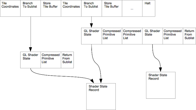
- Link all of the tile sublists from this new list. For each tile, add three commands to the main list: a “Tile Coords” command, a “Branch to Sub-List” command (p. 66), and a “Store Tile Buffer” command (p. 67). I’ll discuss the Store Tile Buffer command later.
- At the end of the list, put a “store tile plus end of frame command”
The result looks something like this:

Rendering Pass
The CPU starts the rendering pass by writing the control register to start the Control List Executor on the newly created control list. To make sure all functional units (like the Primitive Tile Binner) are fully utilized, the binning pass for the next frame starts running at the same time as the rendering pass for the current frame. The Control List Executor has two threads which execute these control lists concurrently.

The rendering pass starts out like the binning pass. The Vertex Cache Manager reads vertices into Vertex Pipe Memory and submits a request to the QPU scheduler. This now runs the full vertex shader, which computes the vertex attributes (this includes redundantly recomputing the vertex positions) and copies them into Vertex Pipe Memory.
The Primitive Setup Engine fetches these shaded vertex parameters from Vertex Pipe Memory. For each triangle, it computes coefficients that will allow it to compute varyings and writes them into the Interpolator inside the QPU. It also causes the Front End Pipe to start rasterizing the triangle. This spits out coordinates for quads (2x2 groups of fragments), coverage masks, and 1/w for each fragment. When it has collected four quads (16 fragments total) it signals the QPU scheduler to start the fragment shader.
The fragment shader reads the interpolated varyings in order from register 35 (VARYING_READ). These come from the Interpolator. As described in page 51 “Varyings Interpolation,” these are partial varyings VP=(A(x-x0)+B(y-y0)). The shader needs to do the rest of the work to compute the varying VP*W+C (The multiplication by W is used to compute the varying in a perspective correct manner; A and B are computed based on the parameter value at each vertex divided by W). The W value is read from register 15-A. The C coefficient is automatically loaded into r5 when the program reads the VARYING_READ register.
If the shader performs a texture lookup, it writes registers 56-63 (TMUn_B, TMUn_S, TMUn_T, TMUn_R) to set the desired texel position. When it writes TMUn_S, the Texture and Memory Unit will start the texture lookup as a side effect. The shader reads the texel from accumulator register r4 after the texture unit has loaded it. The texture unit reads its configuration (size, format, wrap, etc, p. 41) from uniform values in Uniform Memory.
When the fragment shader finishes, it writes the color values to the Tile Buffer using register 46-A (TLB_COLOUR_ALL).
Assuming the following fragment shader, once again in GLSL:
uniform sampler2D tex;
varying vec2 fragTexCoord;

void main()
{
    gl_FragColor = texture2D(tex, fragTexCoord);
}
The generated shader code would presumably look like this:
    .set VARYING_READ, ra35    # p. 52
    .set W, ra15               # p. 51
    .set TMU0_T, ra57          # p. 44
    .set TMU0_S, ra60

    # Compute fragTexCoord.s
    fmul r0, VARYING_READ, W   # VP * W
    fadd r0, r0, r5            # + C

    # Compute fragTexCoord.t
    fmul r1, VARYING_READ, W   # VP * W
    fadd r1, r1, r5            # + C

    # Send to texture unit
    mov TMU0_T, r1             # Set T
    mov TMU0_S, r0             # Set S and start fetch

    # Wait for the texel fetch, sig bits = 10 (p. 29)
    ldtmu0

    # Write fetched texel to tile buffer
    # XXX the documentation mentions locking and unlocking
    # the scoreboard, which I ignore here.
    move TLB_COLOUR_ALL, r4

    exit                       # End program. sig bits = 3 (p. 29)
At the end of each tile’s command list, the Store Tile Buffer command the CPU added to the end of the list causes the tile buffer to copy its contents back out to system memory (this is referred to as the ‘resolve’ operation on some GPUs)
Once all tiles are rendered, the frame is finished. The driver frees the rendering control lists for the current frame. The next frame is already most if not all of the way through its binning pass at that point.