Lost in Translation
I sometimes sympathize with Mike Mulligan, staring up from the bottom of his freshly dug basement at four neat walls and four neat corners and realizing he’s forgotten to leave a way out. The advantage of construction in the virtual world is that it’s easy to back up and start over. Sometimes my approach to a complex new feature is to implement until I run into a dead end, revert my changes, and think about it some more. It’s not uncommon for me to make several runs at a feature, each time building a better mental model of the problem.
I recently added virtual memory support to my GPGPU. I had tried to implement this in the previous version of the microarchitecture, but ran into some problems. The biggest was the translated address was not available at the point in the pipeline where it enqueued stores. One of the most common design problems I run into involves which results are available at which stage of the pipeline.
That was one of many things I learned creating the first design. Heeding Carmack’s Law, I redesigned the entire microarchitecture from scratch last year. One of my design goals was to make it easier to implement virtual memory.
Implementation
I’ll briefly describe how the caches worked in the pre-MMU architecture and how I modified them to support virtual memory. This is a pretty standard design, and there are many web pages and books that describe these concepts in better detail.
The cache is set-associative. A memory address is treated as follows (assuming the default 16k, 4-way cache size for this design):
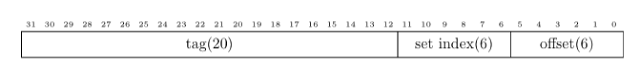
In the original pipeline, a cache access occurs in two stages. The first stage reads from tag SRAM (which contains the upper 20 bits of the addresses of cached lines), using the set index bits from the address. The result from SRAMs is available a cycle later at the next pipeline stage. That compares the tag from the requested address to the one read from SRAM. If they match, the data is in the cache, otherwise it is not. To reduce collisions, it checks four tag RAMs (‘ways’) in parallel.
The first stage of the new architecture works like the old one, using the virtual address to read tag memory. However, it also sends the top bits of the address to the translation lookaside buffer (TLB) in parallel. The TLB is a cache of virtual to physical address mappings. The next stage now compares the translated tag from the TLB against the values read from tag RAM. So, the set index is from the virtual address, but the tag is from the (translated) physical address, an arrangement that is known as “virtually indexed/physically tagged.” There are separate TLBs for instructions and data, as they are accessed from different places in the pipeline.
I’ve opted for a software managed TLB for this iteration. When a virtual address is not present in the TLB, the processor raises a fault, which dispatches a software routine to put the proper address mapping into the TLB. However, nothing about the way I’ve implemented this precludes performing this lookup in hardware later.
A Brief Interrupt
When a hardware thread dispatches a trap, the processor saves the current program counter into a control register, then sets the program counter to the fault handler. The code in the fault handler must save any general purpose registers it needs to use and restore them before returning. Most operating systems switch to a different stack before saving state to enforce memory protections.
I had already implemented faults, but the interrupt service routine in my tests returned without doing anything interesting. As I implemented a TLB miss handler, I realized there was a problem. Because this is a load-store architecture, it can only perform memory stores using pointer registers. It must clobber a register to save registers, which is a chicken and egg problem.
I was familiar with ARM’s solution to this problem, which is to have separate copies the stack and return address registers that it switches to when in an interrupt handler. That wouldn’t be hard to implement, but I felt like it was more complex than it needed to be.
Curious how MIPS implemented this, I did a little research. Searching the web for anything about MIPS generally returns two types of results: slides from computer architecture classes, and questions on Stack Overflow from students trying to understand them. While most didn’t give the level of detail I was looking for, I eventually found the answer: The MIPS ABI reserves two general purpose registers (k0 and k1, registers 26 and 27) which interrupt handlers are free to clobber. As they can be overwritten at any time, the compiler avoids allocating them for user space programs. Although this is probably the simplest solution, I don’t like it much. It seems messy.
The x86 implemention is a bit more… well… I hesitate to use the word ‘simple’ with anything to do with x86. But saving the state in the ISR is easier. The hardware automatically changes the stack pointer to an interrupt handler stack. The ISR can then use the push instruction to save the remaining registers.
At this point, I was running out of steam on my research project, so I ended up reserving two control registers as scratchpads. I transfer two general purpose registers into those control registers when entering the ISR, and transfer them back from them when exiting.
The processor disables the MMU for the current thread when a TLB miss occurs. This avoids another chicken-and-egg problem: TLB misses occurring in the TLB miss handler. The processor saves the previous MMU enable state in the flags control register and restores it when it executes the ‘eret’ (return from exception) instruction.
eret
With that out of the way, I implemented some unit tests and resolved a few bugs. It seemed to be working correctly. To measure the performance impact of adding virtual memory with a more realistic workload, I added a TLB miss handler to my teapot test that “identity mapped” memory (made every virtual address map to the same physical address). That way, I could measure the rough impact of TLB misses without making any other code changes. Here’s the output from the emulator:
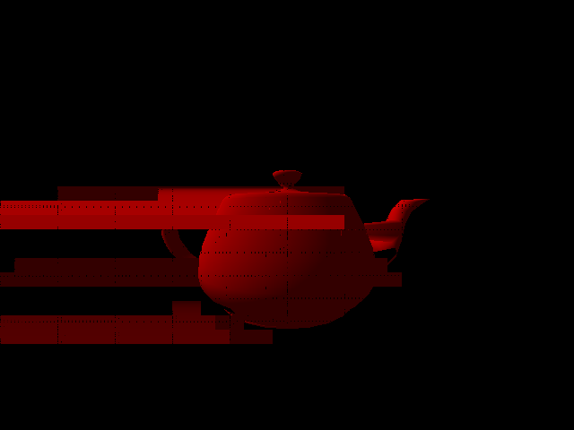
Those with a sharp eye may be able to spot the subtle rendering artifacts…
Something was obviously not right. I added assertions into the code to ensure it was mapping every virtual address to the same physical address, and they all matched. This suggested there was something wrong with TLB fault handler. I verified that it was saving and restoring the registers correctly, and that it was returning to the correct address. At this point, I was stumped.
I tried running it in Verilog simulation, and it crashed on this instruction:
17c8: 00 60 00 bc load_gath_mask v0, s24, (v0)
Then I realized what the problem was, and it was a Mike Mulligan bug.
The load_gath (load gather) instruction treats each lane in the source vector register as a pointer. It loads a 32-bit wide value from each address and puts it into the corresponding lane in the destination register. Because these pointers aren’t necessarily on the same cache line, this instruction isn’t guaranteed to complete in one cycle. So it issues the instruction 16 times (one for each lane) with an associated signal that indicates which lane the instruction is for.
The problem was that the TLB miss occurred after the instruction had already loaded some of the lanes. When that happened, the emulator incorrectly skipped the lane that caused the miss and continued from the next lane after the TLB miss handler returned. This is why it corrupted the image. I confirmed this by hacking it so it would resume from the lane that caused the fault. The hardware implementation started over from the first lane. This was a problem when the pointer register was the same as the destination register. When it restarted the instruction, it had already updated the first lane, which was no longer a valid pointer.
I had actually already run into this problem when I added support for interrupts. I worked around it at that time by waiting until multi-cycle instructions were complete before dispatching the interrupt. But that’s not an option for a fault, which must be “precise.” The proper fix was to save which lane it was processing and restore it before the handler returned. Since a real kernel may context switch in an interrupt handler, software needs to be able to get and set the current lane. This isn’t specific to the TLB miss handler: even if I used hardware to fill the TLB, a page fault could occur in the middle of a scatter/gather memory transfer.
I solved this with a new control register. When a multi-cycle instruction faults, it copies the current lane in the control register, and the ‘eret’ (return from exception) instruction restores it from there. Software can copy this control register into and out of general purpose register, where the handler can copy it into and out of a thread context. I’m not enamored with the solution, but it is at least correct.
TLB miss collisions
The threads share the TLB as they do other resources on the core. While one thread is executing the TLB miss handler routine, it’s possible for another thread to have a TLB miss on the same page. The TLB does not check if a virtual address is already cached when inserting a new entry. Without any other form of synchronization, this could result in multiple TLB entries with the same virtual address, which is bad for a number of reasons.
One approach to resolve this would be to wrap a spinlock around the TLB miss routine, and have it check if the TLB entry is already present when it acquires the lock. This would be less efficient because it serializes misses. Spinlocks are also inefficient for synchronizing between threads, because the waiting thread steals cycles from the thread it is waiting for.
But the other question was how to read the TLB. I used control registers to insert new entries into the TLB. Control registers are convenient because they’re less complex than adding new instructions. But the stage that reads the control registers is after the stage that reads the TLB. If it wanted to read the TLB from a control register, the TLB would need to have two read ports (since there could be a memory access instruction after the control register instruction, with both trying to read the TLB).
I didn’t feel like this was worth the area hit of another port. To do it with one port, I’d need an instruction that goes through the memory pipeline and accesses the TLB like other memory instructions. But if I was going to go through the hassle of creating a new instruction, why not just implement an instruction to insert entries into the TLB that detects if the entry is already present, and just updates it if so? Although there is a little extra overhead in the TLB miss routine to do a page table lookup if the entry is already present, it is less than locking and reading the current value from software.
This turned out to be a pretty big rework, but the new software interface is much cleaner.
Performance
With that changed, the teapot rendered correctly. My new TLB miss handler that identity maps memory looks like this:
                  .globl tlb_miss_handler
tlb_miss_handler: setcr      s0, 11     # Save s0 in scratchpad
                  setcr      s1, 12     # Save s1
                  getcr      s0, 5      # Get fault virtual address
                  getcr      s1, 3      # Get fault reason
                  cmpeq_i    s1, s1, 5  # Is ITLB miss?
                  btrue      s1, fill_itlb # If yes goto update ITLB
fill_dltb:        getcr      s1, 5      # Get virtual address
                  dtlbinsert s1, s0     # Put into DTLB
                  goto       done
fill_itlb:        getcr      s1, 5      # Get virtual address
                  itlbinsert s1, s0     # Put into ITLB
done:             getcr      s0, 11     # Restore saved s0
                  getcr      s1, 12     # Restore saved s1
                  eret
Here are the TLB miss rates with different configurations using the teapot renderer. I’m only measuring the data TLB here, since it is touching more memory. The TLB uses a set associative arrangement. Note that there is only one data point for 1 way (512 entries). If I reduced the number of entries below this, the program livelocked. The four threads kept clobbering the mappings the other ones had entered, then faulted again as soon as they returned.
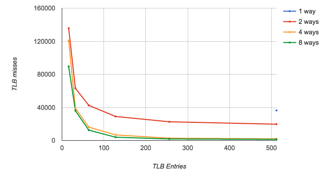
The horizontal scale is a bit weird here. The tick marks on the lines correspond to 16, 32, 64, 128, 256, and 512 entries..
I then ran the teapot test in hardware simulation with 64 TLB entries and four sets for both the instruction and data TLBs. With the address translation disabled, this program takes 10,947,136 cycles. Enabling it increases the execution time to 11,260,776 cycles, about 2.6% slower.